Physics Notes Form 4
Physics Notes Form 4
Physics Form Four Notes
Chapter One
Thin Lences
A lens is conventionally defined as a piece of glass which is used to focus or change the direction of a beam of light passing through it.
They are mainly made of glass or plastic. Lens are used in making spectacles, cameras, cinema projectors, microscopes and telescopes.
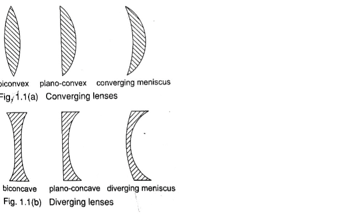
Types of thin lenses.
A lens which is thicker at its centre than at its edges converges light and is called convex or converging lens.
A lens which is thicker at its edges than at its centre diverges light and is known as concave or diverging lens.
Properties of lenses.
1. Optical centre – this is the geometric centre of a lens which is usually shown using a black dot in ray diagrams. A ray travelling through the optical centre passes through in a straight line.
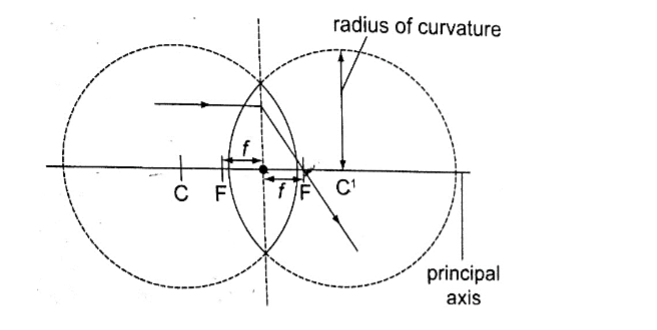
2. Centre of curvature – this is the geometric centre of the circle of which the lens surface is part of. Since lenses have two surfaces there are two centres of curvature. C is used to denote one centre while the other is denoted by C1.
3. Principal axis – this is an imaginary line which passes through the optical centre at right angle to the lens.
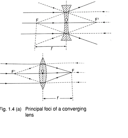
4. Principal focus – this is a point through which all rays travelling parallel to the principal axis pass after refraction through the lens.
A lens has a principal focus on both its sides. F is used to denote the principal focus
5. Focal length – this is the distance between the optical centre and the principal focus. It is denoted by ‘f’.
The principal focus for a converging lens is real and virtual for a diverging lens.
It is important to note that the principal focus is not always halfway between the optical centre and the centre of curvature as it is in mirrors.
Images formed by thin lenses.
The nature, size and position of the image formed by a particular lens depends on the position of the object in relation to the lens.
Construction of ray diagrams
Three rays are of particular importance in the construction of ray diagrams.
1. A ray of light travelling parallel to the principal axis passes through the principal focus on refraction through the lens. In case of a concave lens the ray is diverged in a way that it appears to come from the principal focus.
2. A ray of light travelling through the optical centre goes un-deviated along the same path.
3. A ray of light travelling through the principal focus is refracted parallel to the principal axis on passing through the lens. The construction of the rays is illustrated below.
Images formed by a converging lens.
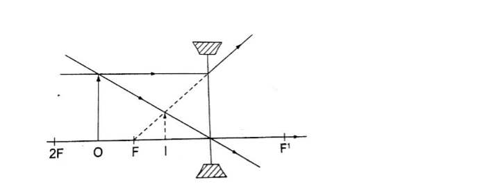
1. Object between the lens and the principal focus.
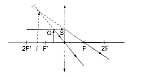
– Image formed behind the object
– Virtual
– Erect
– Magnified
2. Object at infinity.
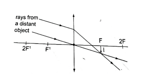
– Image formed at the principal focus of the lens
– Real
– Inverted
– Diminished
3. Object at the principal focus (at F).
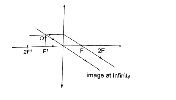
– Image is at infinity.
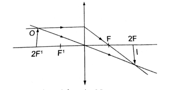
4. Object between the principal focus (F) and 2 F.
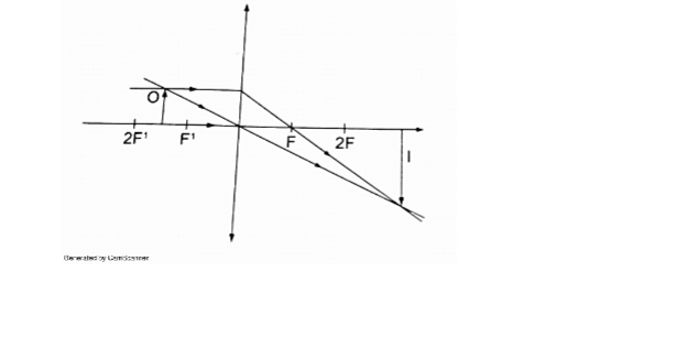
– Image situated beyond 2 F
– Real
– Inverted
– Magnified
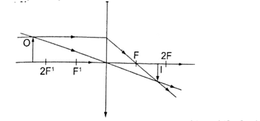
5. Object at 2 F.
– Image is formed at 2 F
– Real
– Inverted
– Same size as the object
6. Object beyond F.
– Image moves nearer to F as object shifts further beyond 2 F
– Real
– Inverted
– Diminished
Images formed by a diverging lens.
Images formed by diverging lens are always erect, virtual and diminished for all positions of the object.
Linear magnification.
The linear magnification produced by a lens defined as the ratio of the height of the image to the height of the object, denoted by letter ‘m’, therefore;
m = height of the image / height of the object.
Magnification is also given by = distance of the image from the lens/ dist. of object from lens. m = v / u
Example
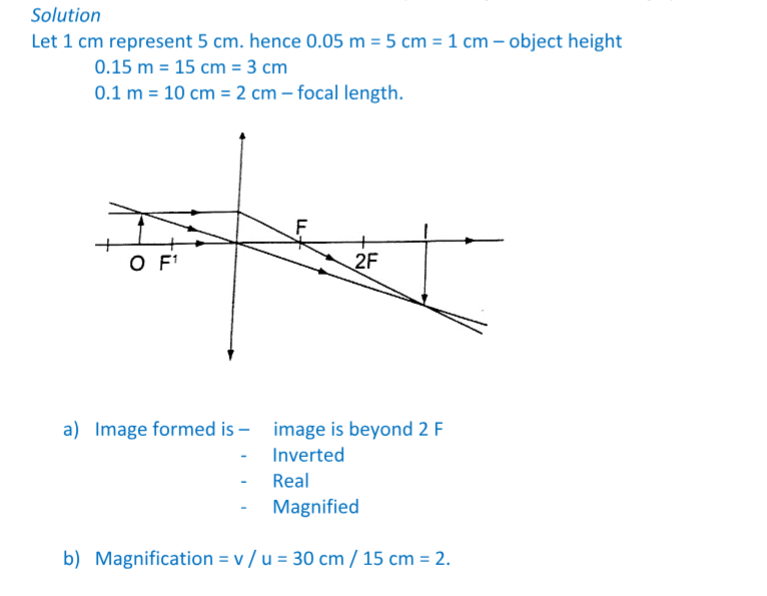
An object 0.05 m high is placed 0.15 m in front of a convex lens of focal length 0.1 m.
Find by construction, the position, nature and size of the image. What is the magnification?
Solution
The lens formula
Let the object distance be represented by ‘u’, the image distance by ‘v’ and the focal length by ‘f’, then the general formula relating the three quantities is given by;
1 / f = 1 / u + 1 / v – this is the lens formula.
Examples
1. An object is placed 12 cm from a converging lens of focal length 18 cm. Find the position of the image.
Solution
Since it is a converging lens f = +18 cm (real-is-positive and virtual-is-negative rule)
The object is real therefore u = +12 cm, substituting in the lens formula, then
1 / f = 1 / u + 1 / v or 1 / v = 1 / f – 1 / u = 1 / 18 – 1 / 12 = – 1 / 36
Hence v = – 36 then the image is virtual, erect and same size as the object.
2. The focal length of a converging lens is found to be 10 cm. How far should the lens be placed from an illuminated object to obtain an image which is magnified five times on the screen?
Solution
f = + 10 cm m = v / u = 5 hence v = 5 u
Using the lens formula 1 / f = 1 / u + 1 / v => 1 /10 = 1 / u + 1 / 5 u (replacing v with 5 u)
1 / 10 = 6 / 5 u, hence 5 u = 60 giving u = 12 cm (the lens should be placed 12 cm from the illuminated object)
3. The lens of a slide projector focuses on an image of height 1.5m on a screen placed 9.0 m from the projector.
If the height of the picture on the slide was 6.5 cm, determine, a) Distance from the slide (picture) to the lens
b) Focal length of the lens
Solution
Magnification = height of the image / height of the object = v / u = 150 / 6.5 = 900 / u
u = 39 cm (distance from slide to the lens). m = 23.09
1 / f = 1 / u + 1 / v = 1 /39 + 1 / 90 = 0.02564 + 0.00111
1 / f = 0.02675 (reciprocal tables)
f = 37.4 cm.
Determining focal lengths.
1. Determining focal length of a converging lens
Experiment: To determine the focal length of a converging lens using the lens formula.
Procedure.
1. Set up the apparatus as shown below
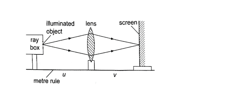
2. Place the object at reasonable length from the screen until a real image is formed on the screen. Move the lens along the metre rule until a sharply focused image is obtained.
3. By changing the position of the object obtain several pairs of value of u and v and record your results as shown.
Discussion
The value u v / u + v is the focal length of the lens and the different sets of values give the average value of ‘f’.
Alternatively the value ‘f’ may be obtained by plotting a graph of 1 / v against 1 / u. When plotted the following graph is obtained.
Since 1 / f = 1 / u + 1 / v, at the y-intercept 1 / u = 0, so that 1/ f = 1 / v or f = v. The focal length may therefore be obtained by reading off the y-intercept and finding the reciprocal.
Similarly at the x-intercept, 1 / v = 0, therefore 1 / f = 1 / u or f = u hence the focal length can also be obtained by reading off the x-intercept and finding the reciprocal.
Uses of lenses on optical devices
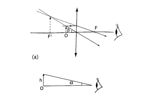
1. Simple microscope – it is also referred to as magnifying glass where the image appears clearest at about 25 cm from the eye.
This distance is known as the least distance of distinct vision (D) or near vision.
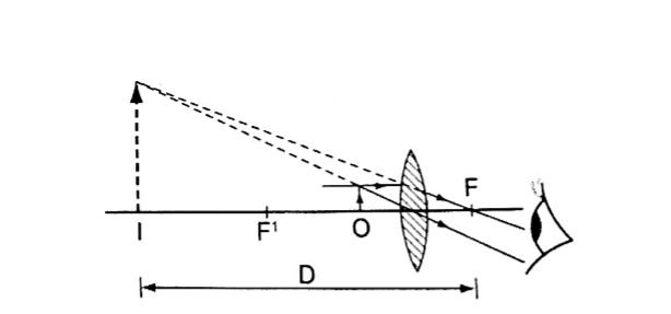
Magnification in a simple microscope
Magnification produced depends on the focal length of the lens. Lens of short focal give greater magnification than those of long focal length.
The angle ϐ subtended by the image at the eye is much greater than α which is the angle that the object would subtend at the eye when viewed without the lens.
The ratio of the ϐ toα is known as angular magnification or magnifying power of an instrument. The angular magnification is equal to linear magnification.
Uses of a simple microscope
1. To study the features of small animals in biology
2. To look closely at small print on a map
3. To observe crystals in physics and chemistry
4. For forensic investigation by the police
2. Compound microscope – It consists of two lenses with one nearer the object called the objective lens and the other nearer the eye called the eyepiece lens.
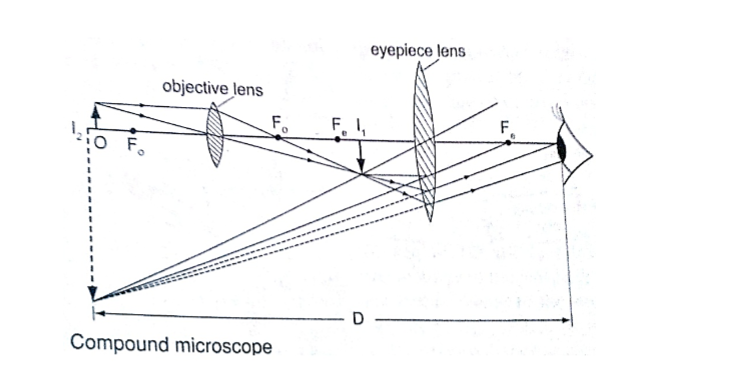
Uses of compound microscope
1. Used to observe Brownian motion in science
2. To study micro-organisms and cells in biology
3. Analyze laboratory tests in hospital.
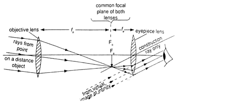
4. The astronomical telescope –It is used to view distant stars. It consists of two lenses; objective and eye-piece lenses. The objective lens has a large focal length while the eye-piece lens has a much shorter focal length.
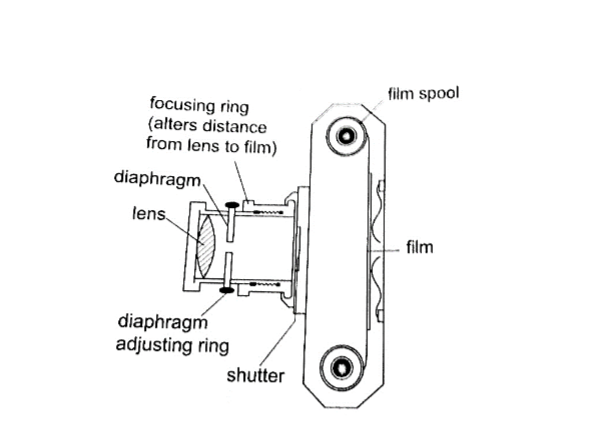
5. The camera – consists of a converging lens system, clicking button, shutter, diaphragm and a mounting base for the film all enclosed in a light proof box.
The distance is adjusted to obtain a clear focus.
The diaphragm has a hole called the aperture with an adjusting control knob to control the amount of light entering the camera. The shutter opens to allow light and close at a given time interval.
Uses of a camera
1. The sine camera is used to make motion pictures
2. High speed cameras are used to record movement of particles
3. Close circuit television cameras (CCTV) are used to protect high security installations like banks, supermarkets etc.
4. Digital cameras are used to capture data that can be fed to computers.
5. Human eye – It consists of a transparent cornea, aqueous humour and a crystal-like lens which form a converging lens system. The ciliary muscles contract or relax to change the curvature of the lens.
Though the image formed at the retina is inverted the brain ‘sees’ the image as upright.
For distant objects ciliary muscles relax while near objects it contracts to control the focal length and this is known as accommodation. When at 25 cmaway an object appears clearest and this is known as least distance of vision or near point.
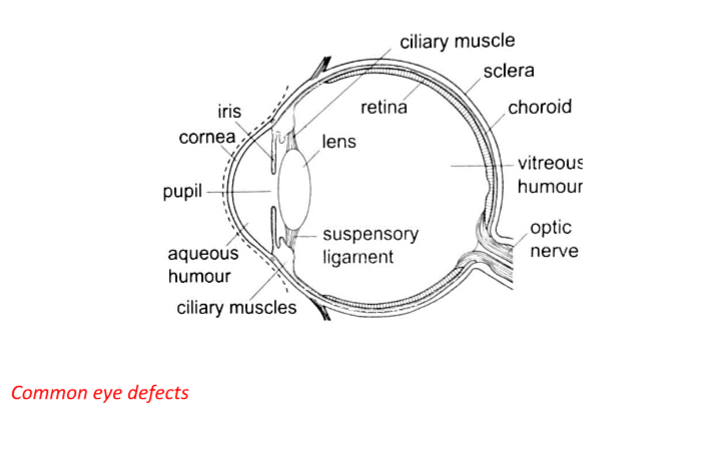
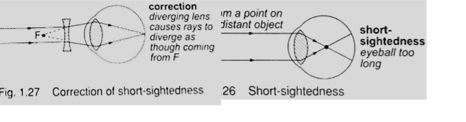
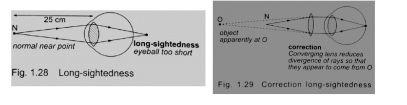
Common eye defects
1. Short sightedness or hypermetropia– the eyeball is too large for the ‘relaxed focal length’ of the eye. The defect is corrected by placing a concave lens in front of the eye.
2. Long sightedness or myopia – images are formed beyond the retina. The defect is corrected by placing a converging lens in front of the eye.
3. Presbyopia – this is the inability of the eye to accommodate and this occurs as the eye ages due to the weakening of the ciliary muscles. It can be corrected by the use a pair of spectacles.
4. Astigmatism – this is a defect where the eye has two different focal lengths as a result of the cornea not being spherical. Corrected by the use of cylindrical lens.
5. Colour blindness– caused by deficiency of colour detecting cells in the retina.
Power of lens
The power of a simple lens is given by the formula: Power = 1 / f. The unit for power of a lens is diopter (D).
Example
Find the power of a concave lens of a focal length 25 cm.
Solution
Power = 1 / f = 1 / -0.25 = -4 D.
Chapter Two
Uniform Circular Motion
Introduction
Circular motion is the motion of bodies travelling in circular paths. Uniform circular motion occurs when the speed of a body moving in a circular path is constant. This can be defined as motion of an object at a constant speed along a curved path of constant radius. When acceleration (variation of velocities) is directed towards the centre of the path of motion it is known as centripetal acceleration and the force producing this centripetal acceleration which is also directed towards the centre of the path is called centripetal force.
Angular motion
This motion can be described as the motion of a body moving along a circular path by giving the angle covered in a certain time along the path of motion.
The angle covered in a certain time is proportional to the distance covered along the path of motion.
The radian
One radian is the angle subtended at the centre of the circle by an arc of length equal to the radius of the circle. Since one circle = 3600and has 2 π radians therefore 1 radian = 3600 / 2 π r= 57.2960 or 57.30.
Example
A wheel of radius 50 cm is rolled through a quarter turn. Calculate
(i) The angle rotated in radians
(ii) The distance moved by a point on the circumference.
Solution
(i) A quarter turn = 3600 / 4= 900. Since 3600 = 2 π radians.
Alternately since 1 radian = 57.30 hence 900 = 1.57 radii.
(ii) A point on the circumference moves through an arc,
Arc = radius ×θ (θ in radians)
= 50 cm × 1.57
= 78.5 cm.
Angular velocity
If a body moving in a circular path turns through an angle θ radians in time ‘t’, we define angular velocity omega (ω), as the rate of change of the angle θ with time.
ω= θ / t, unit for angular velocity is radians per second (rads-1).
Since the radian measure is a ratio we can write it as second-1 (s-1). We can establish the relationship between angular velocity ‘ω’ and linear velocity ‘v’, from the relation, θ = arc / radius, arc = radius × θ.Dividing the expression by ‘t’, then arc / t = radius, but arc / t = v (angular velocity). So ‘v’ = radius × ω. This expression gives us the relationship between angular and linear velocity.
Angular acceleration
If the angular velocity for a body changes from ‘ω1’ to ‘ω2’, in time ‘t’ then the angular acceleration, α can be expressed as;
α= (ω2 – ω1) / t
Units for angular acceleration are radians per second squared (rad s-2) or second-2 (s-2). When α is constant with time, we say the body is moving with uniform angular acceleration. Note: In uniform circular motion α is equal to zero.
To establish the relationship between angular acceleration and linear acceleration, from the relation, v = radius × ω, then dividing by ‘t’, we get (v / t) = radius × ω / t. But v / t = a (linear acceleration) and ω / t = α (angular acceleration). So a = radius × α.
Centripetal force.
This is a force which acts on a body by directing the body towards its centre. Since the direction is continuously changing, the velocity therefore cannot be constant.
Applying Newton’s law of motion (F = ma), the centripetal force Fc is given by;
Fc = ma = mv2/R. Since v = radius ω, then
Fc = mv2 – ω2/R = mRω2.
The centripetal acceleration ‘a’ in relation to angular velocity, ω, is given by a = Rω2.
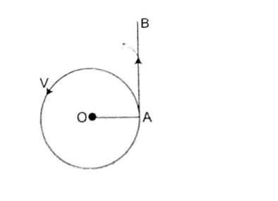
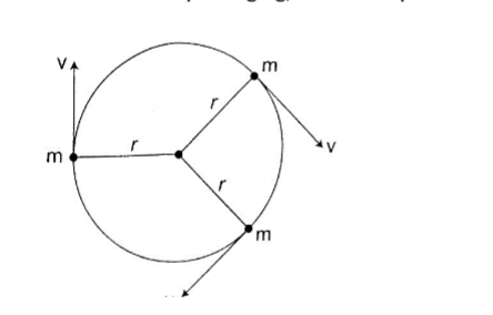
Motion in a vertical circle
Consider a mass ‘m’ tied to a string of length ‘r’ and moving in a vertical circle as shown below.
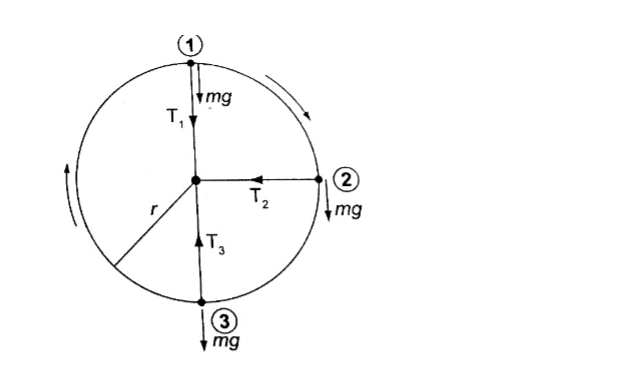
At position 1– both weight (mg) and tension T are in the same direction and the centripetal force is provided by both, hence T1 + mg = mv2/r.
T1 = mv2/r – mg.(The velocity decreases as T1decreases since mg is constant).
T1will be zero when mv2/r = mg and thus v = – this is the value of minimum speed at position 1 which keeps the body in a circle and at this time when T = 0 the string begins to slacken.
At position 2 – the ‘mg’ has no component towards the centre thus playing no part in providing the centripetal force but is provided by the string alone.
T2 = mv2/r
At position 3 – ‘mg’ and T are in opposite directions, therefore; T3 – mg = mv2/r; T3 = mv2/r + mg– indicates that the greatest value of tension is at T3 or at the bottom of the circular path.
Examples
1. A ball of mass 2.5 × 10⁻² kg is tied to a string and whirled in a horizontal circular path at a speed of 5.0 ms-2. If the string is 2.0 m long, what centripetal force does the string exert on the ball?
Solution
Fc = mv2/r = (2.5 × 10-2) × 52 / 2.0 = 0.31 N.
2. A car of mass 6.0 × 10³ kg is driven around a horizontal curve of radius 250 m.
if the force of friction between the tyres and the road is 21,000 N. What is the maximum speed that the car can be driven at on a bend without going off the road?
Solution
Fc = force of friction = 21,000, also Fc = mv2/r, hence
21,000 = (6.0 × 10³) × v2 / 250, v2 = (21,000 × 250) /6.0 × 103
3. A stone attached to one end of a string is whirled in space in in a vertical plane. If the length of the string is 80 cm, determine the minimum speed at which the stone will describe a vertical circle. (Take g = 10 m/s2).
2024 FORM 1 2 3 4 REVISION RESOURCES
FORM 1 2 3 4 TERM 1 2 3 OPENER , MID AND END TERM EXAMS
1995-2024 KCSE KNEC PAPERS QUESTIONS,ANSWERS AND REPORT
2008-2024 KCSE FORM 4 COUNTY MOCKS
FORM 1 2 3 4 SCHEMES OF WORK
FORM 1 2 3 4 LESSON PLANS
FORM 1 2 3 4 CLASS REVISION NOTES
FORM 1 2 3 4 TERM 1 2 3 HOLIDAY ASSISNMENTS
FORM 3 4 SETBOOKS STUDY GUIDES
FORM 1 2 3 4 TOPICAL TESTS
FORM 1 2 3 4 REVISION BOOKLETS
LIFE SKILLS NOTES
FORM 1 2 3 4 SYLLABUS
KENYA SCHOOL CODES
HOW TO REVISE AND PASS EXAMS
GUIDANCE AND CONSELLING NOTES
CLICK HERE TO DOWNLOAD ALL LATEST 2024 KCSE REVISION MOCKS
KCSE COUNTY MOCKS DOWNLOADS 2024
2023 KCSE COUNTY MOCKS DOWNLOADS
- 2023 KAPSABET BOYS POST MOCK
- PANGANI MOCK KCSE 2023
- KCSE 2023 LAINAKU II FORM 4 JOINT MOCK
- KENYA HIGH POST MOCK
- KALA MOCK =Password is- subjectcodeKALA2023
- KCSE 2023 SAMIA JOINT MOCK
LANJET 2023 EVALUATION MOCK
2023 EVALUATION MOCK nyandarua trial 4
2023 EVALUATION MOCK nyandarua trial 3
KCSE 2023 MOCKS NYARIRA CLUSTER EXAMS
KCSE 2023 CEKANA MOCKS
KCSE 2023 ACHIEVERS JOINT MOCK
- KAPSABET 2 MOCK 2023
- MOKASA 2 MOCK 2023
- 2023 Mang’u high revision mock
- FORM 4 TERM 2 BAKALE EXAM
CATHOLIC DIOCESE OF KAKAMEGA MOCK
- BSJE JOINT MOCK EXAM 2023
- MARANDA HIGH SCHOOL MOCK JUNE
- KCSE 2023 mock Nginda girls
- 2023 Kcse mock Wahundura
- 2023 Kcse mock set 22
KCSE 2023 KASSU MOCK EXAMS
- 2023 KCSE EAGLE TRIAL 1 MOCK
- 2023 lainaku revision mock
- 2023 FORM 4 evaluation exams set 18
- 2023 FORM 4 evaluation exams set 17
- 2023 FORM 4 evaluation exams set 16
LUGARI CONSTITUENCY -MOCK 1
- 2023 KCSE FORM 4 EVALUATION TEST
2023 mokasa mocks revision exams
- SUKELLEMO JOINT PRE-MOCK EXAMS
- Mumias west pre mock kcse exams
- 2023 SUNRISE PRE-MOCK
- 2023 kcse arise and shine pre-mock
- MECS CLUSTER JOINT MOCK EXAM
- Chogoria murugi zone pre-mock
- MOMALICHE 2 EXAMS PRE MOCK
- ASUMBI PRE MOCK EXAMS 2023
- 2023 MARANDA HIGH PRE-MOCK
- KAPSABET INTERNAL TRIAL 1 2023
- FORM 4 EVALUATION TEST 2023
- 2023 FORM 4 evaluation exams
Mock exams and pre-mock exams are practice tests that are taken before the actual exams.
2022 COUNTY MOCKS 38 EXAMS
2021-22 COUNTY MOCKS 36 EXAMS
2020-21 COUNTY MOCKS 24 EXAMS
2019 COUNTY MOCKS 44 EXAMS
2018 COUNTY MOCKS 23 COUNTIES EXAMS
2017 COUNTY MOCKS 25 COUNTIES EXAMS
2016 COUNTY MOCKS 16 COUNTIES
2015 COUNTY MOCKS 20 COUNTIES
2008 , 2009 , 2010 , 2011 , 2012 , 2013, 2014 COUNTY MOCKS 25 COUNTIES
2023 KCSE COUNTY MOCKS Mock exams and pre-mock exams are practice tests that are taken before the actual exams.
They are designed to help students get a sense of what to expect in the real exam and to identify areas where they need to improve.
The purpose of taking mock exams is to help students build confidence, develop test-taking strategies, and identify their strengths and weaknesses.
Pre-mock exams are usually taken a few weeks or months before the actual exam, while mock exams are usually taken closer to the exam date.